Contents
- 9.0 Introduction
- 9.1 Cycles Per Hour
- 9.2 Excessive Downtime
- 9.3 Impact Detection
- 9.4 Offline Detection
- 9.5 PM – Cycle Count
- 9.6 PM – Runtime
- 9.7 PM – Stopwatch
- 9.8 Telemetry
- 9.9 Utilization
- 9.10 Utilization – End of Shift
9.0 Introduction
There are 10 different types of alarms are available for use:
- Cycles Per Hour
- Excessive Downtime
- Impact Detection
- Offline Detection
- PM – Cycle Count
- PM – Runtime
- PM – Stopwatch
- Telemetry
- Utilization
- Utilization – End of Shift
You can choose to be alerted either by email or by text. If choosing text notification, you must enter your mobile phone number under personal settings as outlined in the Managing Personal Settings configuration section. A high level overview of viewing and creating alarms is available in the Managing Alarms configuration section, and a description of setting up each individual alarm type is listed below.
9.1 Cycles Per Hour
This type of alarm triggers when a piece of equipment fails to meet the defined number of cycles per hour, with the option to restrict the alarm to only times when the equipment is scheduled to run. The settings for this alarm are indicated below, followed by a description of what each setting does.

Figure 9.1.1 – Cycles Per Hour Alarm Settings
- Equipment – This is a drop down list that will be populated with all the equipment this alarm can be added for. When adding an alarm at the department level, the equipment list will be limited to only the equipment contained within that department. When at the equipment detail level, this drop down will be set to the current equipment and locked so that it cannot be changed.
- Alarm Type – This sets the type of alarm that will be added for the equipment. In this case we are adding a Cycles Per Hour alarm, and so that should be selected.
- # of Cycles – The number of cycles required per hour. Anything less than this value will trigger the alarm. Setting this value too high will cause false alarms on equipment that cannot meet the cycle rate, and setting the value too low will make it harder to diagnose and address machine capacity issues. This alarm will still trigger even when the equipment is down for a legitimate reason (i.e. planned preventive maintenance).
- Restrict to Schedule? – Checked by default. When checked, the alarm is only active when the equipment is scheduled to run. The entire previous hour must fall within scheduled time for this alarm to be triggered when this option is checked. When unchecked the alarm will be active 24 hours a day, 7 days a week. This can lead to excessive alarms, but is useful in scenarios where a piece of equipment needs to be running at full capacity for an extended period to meet a production quota.
- Subscribe? – This allows a user to subscribe to the alarm via Text message, Email, or both. This setting will only be effective for the currently logged in user, and that user must have a mobile phone number specified in their personal settings to receive text messages. The information (“i”) icon next to the Text message checkbox in the image above shows that the user does not have a mobile phone number set.
9.2 Excessive Downtime
When setting up equipment (see the Building the Company Tree configuration section), an Excessive downtime threshold can be set in seconds. Once this is set, downtimes that are longer than the threshold amount are reported in the Excessive Downtime Report, but can also trigger alarms. Using these alarms can help address equipment capacity issues by allowing organizations to be proactive in investigating excessive downtime occurrences as they happen, rather than after the fact. The settings for this alarm are indicated below, followed by a description of what each setting does.
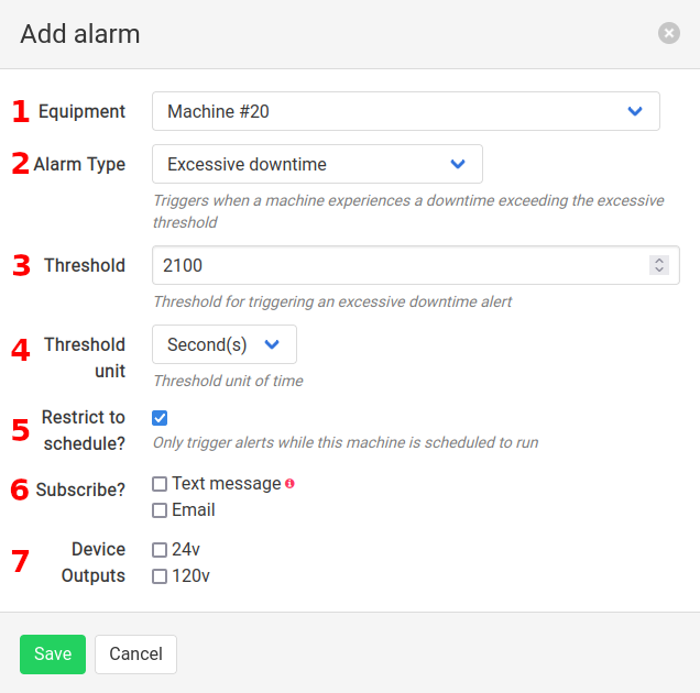
Figure 9.2.1 – Excessive Downtime Alarm Settings
- Equipment – This is a drop down list that will be populated with all the equipment this alarm can be added for. When adding an alarm at the department level, the equipment list will be limited to only the equipment contained within that department. When at the equipment detail level, this drop down will be set to the current equipment and locked so that it cannot be changed.
- Alarm Type – This sets the type of alarm that will be added for the equipment. In this case we are adding a Excessive downtime alarm, and so that should be selected.
- Threshold – Used in conjunction with the Threshold unit setting (#4), this is the value above which the alarm will be triggered. Setting this to 2100 and the Threshold unit to Second(s) means that if the downtime on the equipment becomes longer than 2100 seconds, the alarm will be triggered.
- Threshold Unit – Used in conjunction with the Threshold setting (#3), this sets whether the threshold units are in Second(s), Minute(s) or Hour(s). Setting this to Minute(s) and the Threshold value to 10 would mean that if the downtime on the equipment becomes longer than 10 minutes, the alarm will be triggered.
- Restrict to Schedule? – Checked by default. When checked, the alarm is only active when the equipment is scheduled to run. When unchecked the alarm will be active 24 hours a day, 7 days a week. This can lead to excessive alarms, but is useful in scenarios where a piece of equipment needs to be running at full capacity for an extended period to meet a production quota.
- Subscribe? – This allows a user to subscribe to the alarm via Text message, Email, or both. This setting will only be effective for the currently logged in user, and that user must have a mobile phone number specified in their personal settings to receive text messages. The information (“i”) icon next to the Text message checkbox in the image above shows that the user does not have a mobile phone number set.
- Device Outputs – The Caddis device has two outputs: one 24 VDC and one 120 VAC. This setting allows one or both of those outputs to be turned on when a excessive downtime alarm is triggered. This allows an buzzer, siren or light to be turned on in addition to alerting users via text and email. Select 24v to turn the 24 VDC output on when the alarm is triggered, and 120v to turn on the 120 VAC output during an alarm condition. This should not be used for machine control, only as an indication that an alarm condition has been reached. Caddis Systems does not recommend or support using the Caddis device for machine control scenarios.
9.3 Impact Detection
Triggers when an impact is detected on any of the available axes of an optional accelerometer module. This can be used to detect impact on equipment such as fork trucks to see when they are being used outside of safety and equipment wear specifications. This alarm is only available by request, and may require customization for your situation. Please contact LCM2M sales for more information.
9.4 Offline Detection
LCM2M devices usually go offline for one of two reasons: power failure and network issues. Power failure can result from things like tripped circuit breakers, but can also be the result of power being disconnected from a piece of equipment during planned maintenance. Network issues take many forms including, but not limited to, the following.
- Poor wireless network signal
- Cut or damaged Ethernet cable
- Firewall blocking access to the Internet
- Switches or routers that are offline
For a list of the firewall ports that must be open for LCM2M devices to function properly, see our guide on Getting A New Device Online.
If LCM2M devices are not online, they cannot report the data they are collecting to the LCM2M servers, which prevents you from viewing the data. Offline detection alarms can be set for equipment so that a user can be alerted whenever there is a connection issue. This ensures that any issues in your monitoring infrastructure can be dealt with quickly. The settings for this alarm are indicated below, followed by a description of what each setting does.

Figure 9.4.1 – Offline Detection Alarm Settings
- Equipment – This is a drop down list that will be populated with all the equipment this alarm can be added for. When adding an alarm at the department level, the equipment list will be limited to only the equipment contained within that department. When at the equipment detail level, this drop down will be set to the current equipment and locked so that it cannot be changed.
- Alarm Type – This sets the type of alarm that will be added for the equipment. In this case we are adding a Offline detection alarm, and so that should be selected.
- Threshold – Used in conjunction with Threshold unit (#4), this sets the length of time a device can be offline before this alarm is triggered. If this is set to 300 and Threshold unit is set to Second(s), a device can be offline for 300 seconds before the alarm is triggered.
- Threshold unit – Used in conjunction with Threshold (#3), this sets the units for the threshold. If this is set to Seconds(s) and Threshold is set to 300, a device can be offline for 300 seconds before the alarm is triggered. Possible settings are Second(s), Minute(s) and Hour(s).
- Subscribe? – This allows a user to subscribe to the alarm via Text message, Email, or both. This setting will only be effective for the currently logged in user, and that user must have a mobile phone number specified in their personal settings to receive text messages. The information (“i”) icon next to the Text message checkbox in the image above shows that the user does not have a mobile phone number set.
9.5 PM – Cycle Count
Preventative maintenance alarm which triggers off of the equipment cycle count. Used for when an operations team wants to be alerted to do maintenance on a piece of equipment after a certain number of cycles have occurred. The settings for this alarm are indicated below, followed by a description of what each setting does.

Figure 9.5.1 – PM Cycle Count Alarm Settings
- Equipment – This is a drop down list that will be populated with all the equipment this alarm can be added for. When adding an alarm at the department level, the equipment list will be limited to only the equipment contained within that department. When at the equipment detail level, this drop down will be set to the current equipment and locked so that it cannot be changed.
- Alarm Type – This sets the type of alarm that will be added for the equipment. In this case we are adding a PM – Cycle Count alarm, and so that should be selected.
- Cycle Count – The number of cycles that must occur on the piece of equipment before this alarm is triggered.
- Notes – This field will contain information on what type of maintenance should be performed when this alarm is triggered.
- Subscribe? – This allows a user to subscribe to the alarm via Text message, Email, or both. This setting will only be effective for the currently logged in user, and that user must have a mobile phone number specified in their personal settings to receive text messages. The information (“i”) icon next to the Text message checkbox in the image above shows that the user does not have a mobile phone number set.
9.6 PM – Runtime
Preventative maintenance alarm which triggers off of equipment runtime. Used for when an operations team wants to be alerted to do maintenance on a piece of equipment once it has operated for a specified number of hours. The settings for this alarm are indicated below, followed by a description of what each setting does.

Figure 9.6.1 – PM Runtime Alarm Settings
- Equipment – This is a drop down list that will be populated with all the equipment this alarm can be added for. When adding an alarm at the department level, the equipment list will be limited to only the equipment contained within that department. When at the equipment detail level, this drop down will be set to the current equipment and locked so that it cannot be changed.
- Alarm Type – This sets the type of alarm that will be added for the equipment. In this case we are adding a PM – Runtime alarm, and so that should be selected.
- Runtime Hours – The number of hours that the piece of equipment must operate before this alarm is triggered.
- Notes – This field will contain information on what type of maintenance should be performed when this alarm is triggered.
- Subscribe? – This allows a user to subscribe to the alarm via Text message, Email, or both. This setting will only be effective for the currently logged in user, and that user must have a mobile phone number specified in their personal settings to receive text messages. The information (“i”) icon next to the Text message checkbox in the image above shows that the user does not have a mobile phone number set.
9.7 PM – Stopwatch
Preventative maintenance alarm which triggers after a given period of time, regardless of equipment running/down status, utilization, runtime or any other metrics. This type of alarm can be used on equipment that does not have an attached device. The settings for this alarm are indicated below, followed by a description of what each setting does.

Figure 9.7.1 – PM Stopwatch Alarm Settings
- Equipment – This is a drop down list that will be populated with all the equipment this alarm can be added for. When adding an alarm at the department level, the equipment list will be limited to only the equipment contained within that department. When at the equipment detail level, this drop down will be set to the current equipment and locked so that it cannot be changed.
- Alarm Type – This sets the type of alarm that will be added for the equipment. In this case we are adding a PM – Stopwatch alarm, and so that should be selected.
- Duration – Used in conjunction with Duration unit (#4), this sets the length of time before the alarm is triggered. If this is set to 1 and Duration unit is set to Month(s) it means that the alarm will be triggered every month.
- Duration unit – Used in conjunction with Duration (#3), this sets the units for the duration to be Minute(s), Hours(s), Day(s), Week(s), and Month(s). If this is set to Day(s) and Duration is set to 10, that means the alarm will trigger every 10 days.
- Notes – This field will contain information on what type of maintenance should be performed when this alarm is triggered.
- Subscribe? – This allows a user to subscribe to the alarm via Text message, Email, or both. This setting will only be effective for the currently logged in user, and that user must have a mobile phone number specified in their personal settings to receive text messages. The information (“i”) icon next to the Text message checkbox in the image above shows that the user does not have a mobile phone number set.
9.8 Telemetry
This alarm triggers when the a telemetry value is greater than or less than a given value. This is used to trigger an alarm based on either the temperature or analog input values. A thermocouple must be connected to the Caddis device’s thermocouple port before temperature data can be collected, and a 0-10 VDC sensor must be connected to the analog input before analog data can be collected. The settings for this alarm are indicated below, followed by a description of what each setting does.

Figure 9.8.1 – Telemetry Alarm Settings
- Equipment – This is a drop down list that will be populated with all the equipment this alarm can be added for. When adding an alarm at the department level, the equipment list will be limited to only the equipment contained within that department. When at the equipment detail level, this drop down will be set to the current equipment and locked so that it cannot be changed.
- Alarm Type – This sets the type of alarm that will be added for the equipment. In this case we are adding a Telemetry alarm, and so that should be selected.
- Data Type – Sets whether this alarm will use Temperature or Analog Input data to trigger on. The appropriate thermocouple (type-K) must be connected to the Caddis device’s thermocouple port in order for temperature data to be used, and an appropriate 0-10 VDC analog sensor must be connected to the analog port in order for analog data to be used.
- Operator – This is a logical operator that will be applied to the input value to see if it is greater than or less than the threshold Value (#5). Greater than (>) will cause the alarm to trigger when the input value goes above the threshold, and less than (<) will cause the alarm to trigger when the input value goes below the threshold.
- Value – This is the threshold value used with the operator setting in #4 to trigger the alarm when the input value goes above or below this threshold. If Analog Input is selected from the Data Type drop down, this threshold value will be based on the scaled analog value, not the raw 0-10 VDC analog voltage.
- Sustained For – This is used in conjunction with the Sustained Unit setting from #7. This is the amount of readings or time in seconds that the value must be sustained for. Setting this value appropriately can prevent those subscribed to the alarm from receiving too many notifications or false positives. This is highly dependent on the situation and the sensor that is being used.
- Sustained Unit – This is used in conjunction with the Sustained For setting from #6. When set to Reading(s), the Sustained for number of data samples (set by the telemetry rate) must meet the trigger condition without interruption. If the input value comes back within the threshold limit set for the alarm for even 1 sample, the count will be reset. When set to Seconds, the system will check to see if the value is beyond the threshold limit every time the number of seconds set in the Sustained For field has elapsed. This setting is most useful if it is set to something higher than the telemetry rate.
- Subscribe? – This allows a user to subscribe to the alarm via Text message, Email, or both. This setting will only be effective for the currently logged in user, and that user must have a mobile phone number specified in their personal settings to receive text messages. The information (“i”) icon next to the Text message checkbox in the image above shows that the user does not have a mobile phone number set.
- Device Outputs – The Caddis device has two outputs: one 24 VDC and one 120 VAC. This setting allows one or both of those outputs to be turned on when a telemetry alarm is triggered. This allows an buzzer, siren or light to be turned on in addition to alerting users via text and email. Select 24v to turn the 24 VDC output on when the alarm is triggered, and 120v to turn on the 120 VAC output during an alarm condition. This should not be used for machine control, only as an indication that an alarm condition has been reached. Caddis Systems does not recommend or support using the Caddis device for machine control scenarios.
9.9 Utilization
This alarm is triggered when the utilization for a piece of equipment drops below a threshold over the last period of scheduled time. When adding a new alarm, Utilization can be selected to set up this type of alarm. The settings for the alarm are indicated below, followed by a description of what each setting does.

Figure 9.9.1 – Utilization Alarm Settings
- Equipment – This is a drop down list that will be populated with all the equipment this alarm can be added for. When adding an alarm at the department level, the equipment list will be limited to only the equipment contained within that department. When at the equipment detail level, this drop down will be set to the current equipment and locked so that it cannot be changed.
- Alarm Type – This sets the type of alarm that will be added for the equipment. In this case we are adding a Utilization alarm, and so that should be selected.
- Utilization threshold (%) – If the equipment utilization drops below this value for the time span of the specified period (shown in #4 and #5), the alarm will be triggered. This is evaluated by stepping back in the data history for the length of the period and calculating the utilization for that time period.
- Period – This setting is paired with the next (#5). The period is the number of units to look back in the data history to calculate the utilization for the equipment. If this is set to 1 and Period unit is set to Day(s), the system will look at the previous 1 day of data and use that to calculate the utilization. The schedule for the equipment does effect this calculation so that only scheduled time is taken into account.
- Period unit – This setting is paired with the previous (#4). The period unit is the unit of time to use when looking back in the data history to calculate the utilization for the equipment. If this is set to Hour(s) and the period is set to 1, the system will look at the previous 1 hour of data and use that to calculate the utilization. The schedule for the equipment does effect this calculation so that only scheduled time is taken into account.
- Subscribe? – This allows a user to subscribe to the alarm via Text message, Email, or both. This setting will only be effective for the currently logged in user, and that user must have a mobile phone number specified in their personal settings to receive text messages. The information (“i”) icon next to the Text message checkbox in the image above shows that the user does not have a mobile phone number set.
9.10 Utilization – End of Shift
This alarm is triggered when the shift utilization for a piece of equipment at end of shift is below a specified threshold. When adding a new alarm, Utilization – End of Shift can be selected to set up this type of alarm. The settings for the alarm are indicated below, followed by a description of what each setting does.

Figure 9.10.1 – End of Shift Utilization Settings
- Equipment – This is a drop down list that will be populated with all the equipment this alarm can be added for. When adding an alarm at the department level, the equipment list will be limited to only the equipment contained within that department. When at the equipment detail level, this drop down will be set to the current equipment and locked so that it cannot be changed.
- Alarm Type – This sets the type of alarm that will be added for the equipment. In this case we are adding a Utilization – End of Shift alarm, and so that should be selected.
- Utilization threshold (%) – If the equipment utilization drops below this value for the time span of the specified shift(s), the alarm will be triggered. This is not evaluated until a shift has ended, and shifts must be configured properly in the schedule.
- Shift – This sets which shift(s) the alarm will be active for. If it is set to All shifts, the alarm is active for every shift that is configured in the schedule. If a specific shift is selected, the alarm will only be active for that shift.
- Subscribe? – This allows a user to subscribe to the alarm via Text message, Email, or both. This setting will only be effective for the currently logged in user, and that user must have a mobile phone number specified in their personal settings to receive text messages. The information (“i”) icon next to the Text message checkbox in the image above shows that the user does not have a mobile phone number set.